Hybrid Fibre-Coax
Networks
Hybrid fibre-coaxial (HFC) is a telecommunications
industry term for a broadband network which combines optical fiber and coaxial
cable. It has been commonly employed by many cable TV operators since
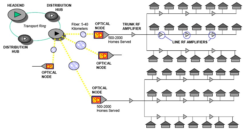
the 1990s. See diagram below for a typical architecture for an HFC Network.
The fiber optic network extends from the cable operators'
master headend, sometimes to regional headends, and out to a neighbourhood's
hubsite, and finally to a fiber optic node which serves anywhere from 25 to 2000
homes. A master headend will usually have satellite dishes for reception of
distant video signals as well as IP aggregation routers. Some master headends
also house telephony equipment for providing telecommunications services to the
community. A regional or area headend will receive the video signal from the
master headend and add to it the Public, Educational and/or Governmental (PEG)
channels as required by local franchising authorities or insert targeted
advertising that would appeal to a local area. The various services are encoded,
modulated and upconverted onto RF carriers, combined onto a single electrical
signal and inserted into a broadband optical transmitter. This optical
transmitter converts the electrical signal to a downstream optically modulated
signal that is sent to the nodes. Fiber optic cables connect the headend or hub
to optical nodes in a point-to-point or star topology, or in some cases, in a
protected ring topology.
A fiber optic node has a broadband optical receiver which converts the
downstream optically modulated signal coming from the headend/hub to an
electrical signal going to the homes. Today, the downstream signal is a radio
frequency modulated signal that typically begins at 50 MHz and ranges from 550
MHz to 1000 MHz on the upper end. The fiber optic node also contains a
reverse/return path transmitter that sends communication from the home back to
the headend. In North America, this reverse signal is a modulated radio
frequency ranging from 5 to 42 MHz while in other parts of the world, the range
is 5 to 65 MHz.
The optical portion of the network provides a large amount of flexibility. If
there are not many fiber optic cables to the node, Wavelength division
multiplexing can be utilized to combine multiple optical signals onto the same
fiber. Optical filters are used to combine and split optical wavelengths onto
the single fiber. For example, the downstream signal could be on a wavelength at
1310nm and the return signal could be on a wavelength at 1550nm. There are also
techniques to put multiple downstream signals on a single fiber by putting them
at different wavelengths.
The coaxial portion of the network connects 25 to 2000 homes (500 is typical) in
a tree-and-branch configuration. Radio frequency amplifiers are used at
intervals to overcome cable attenuation and passive losses caused by splitting
or "tapping" the cable. Trunk coaxial cables are connected to the optical node
and form a coaxial backbone to which smaller distribution cables connect. Trunk
cables also carry AC power which is added to the cable line at usually either
60V or 90V by a power supply and a power inserter. The power is added to the
cable line so that trunk and distribution amplifiers do not need an individual,
external power source. From the trunk cables, smaller distribution cables are
connected to a port of the trunk amplifier to carry the RF signal and the AC
power down individual streets. If needed, line extenders, which are smaller
distribution amplifiers, boost the signals to keep the power of the television
signal at a level that the TV can accept. The distribution line is then "tapped"
into and used to connect the individual drops to customer homes. These taps pass
the RF signal and block the AC power unless there are telephony devices that
need the back-up power reliability provided by the coax power system. The tap
terminates into a small coaxial drop using a standard screw type connector known
as an “F” connector. The drop is then connected to the house where a ground
block protects the system from stray voltages. Depending on the design of the
network, the signal can then be passed through a splitter to multiple TVs. If
too many TVs are connected, then the picture quality of all the TVs in the house
will go down requiring the use of a "drop" or "house" amplifier.
Competitive network technologies
Digital subscriber line (DSL) is a
technology used by traditional telephone companies to deliver
advanced services (high-speed data and sometimes video) over twisted
pair copper telephone wires. It typically has lower data carrying
capacity than HFC networks and data speeds can be range limited by
line lengths and quality.
Satellite television competes very well with HFC networks in
delivering broadcast video services. It usually does not compete
well in delivering Internet data, telephony and interactive services
(i.e. VOD) because it does not have a good method to transport
return-path information.
Analogous to HFC, Fiber In The Loop technology is used by telephone
local exchange carriers to provide advanced services to telephone
customers over the POTS local loop.
External Links
|