| |
Each MPLS
packet/frame has a header that is either encapsulated between the
link layer and the network layer, or resides within an existing
header, such as the virtual path/channel identifier (VPI/VCI) pair
within asynchronous transfer mode (ATM). At most, the MPLS header
will contain
-
·
A
label,
-
·
TTL
field,
-
·
Class of Service (CoS) field,
-
·
Stack indicator,
-
·
Next header type indicator, and
-
·
Checksum.
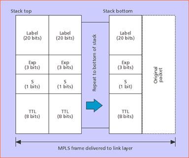
Figure 10 - MPLS
label stack encoding for packet-oriented transport
Figure 10 shows
the structure of the generic MPLS frame. An MPLS label stack of one
or more 32-bit entries precedes the payload (e.g., an IP packet).
The label is 20 bits wide, with 3 additional bits for
experimentation (e.g., to indicate queuing and scheduling
disciplines). An 8-bit time to live (TTL) field is defined to assist
in the detection and discard of looping MPLS packets: the TTL is set
to a finite value at the beginning of the LSP, decremented by one at
every label switch, and discarded if the TTL reaches zero. The S bit
is set to 1 to indicate the final (and possibly only) stack entry
before the original packet; an LSR that pops a stack entry with S
set to 1 must be prepared to deal with the original packet in its
native format
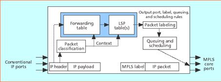
Figure 11 -
Ingress LER
|
|